Description
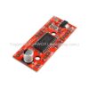
- GND : There are three GND (Ground) pins on the Easy Driver. They are all connected together inside the board. Connect the negative side of your power supply, as well as from any other boards you are using to drive the Easy Driver to one or more of the GND pins.
- M+ : This is the power input to the Easy Driver. Connect this to the positive power supply lead. This should be a 6V to 30V, 2A (or more) power supply that is clean (low ripple).
- A and B : (four pins) These are the motor connections. See below diagrams for how to hook these up. A and B are the two coils of the motor, and can swap the two wires for a given coil (it will just reverse the direction of the motor). Make CERTAIN that this connection to the motor is solid, and NOT through a connector that has any chance of intermittent contact (which will fry the motor driver chip).
- STEP : This needs to be a 0V to 5V (or 0V to 3.3V if you’ve set your Easy Driver that way) digital signal. Each rising edge of this signal will cause one step (or microstep) to be taken.
- DIR (Direction) : This needs to be a 0V to 5V (or 0V to 3.3V if you’ve set your Easy Driver up that way) digital signal. The level if this signal (high/low) is sampled on each rising edge of STEP to determine which direction to take the step (or microstep).


